
| DOWNLOAD PDF |
R. L Gregory
From Concepts and Mechanisms of Perception (1974, London: Duckworth) pp. 501-518 and Nature, 203, 4942, 274-295 with the kind permission of the Editor
[The story behind this idea is, perhaps, of interest in showing how a question can suggest another more interesting question, leading with luck to something unexpected. The question concerned stereoscopic vision, but it led by three or four steps and a few minutes of thought in a darkroom, to the possibility of something quite different - a telescope camera for getting improved pictures of the moon, the planets and the stars. My father, C. C. L. Gregory, was a professional astronomer, and I had been brought up with telescopes and so with the problem of 'seeing' - the problem of the disturbance of telescopic images by atmospheric turbulence. This is beautifully described by Newton (Opticks, 1704) who was pessimistic about any cure. Indeed he said that a cure was simply impossible. But even Newton was not always right in his strictures: he declared that chromatic fringes would for ever beset images given by lenses; not at all foreseeing the invention of achromatic combinations of flint and crown glass lenses (generally attributed to John Dollond; suggested by Chester Moor Hall in 1729 and demonstrated by Samuel Klingen-Steirna in 1758). Newton describes the problem, and the supposed impossibility of cure, in the following passage in Opticks:
If the Theory of making Telescopes could at length be fully brought into Practice, yet there would be certain Bounds beyond which Telescopes could not perform. For the Air through which we look upon the Stars, is in a perpetual Tremor; as may be seen by the tremulous Motion of Shadows cast from high Towers, and by the twinkling of the fix'd Stars. But these Stars do not twinkle when viewed through Telescopes which have large apertures. For the Rays of Light which pass through divers parts of the aperture, tremble each of them apart, and by means of their various and sometimes contrary Tremors, fall at one and the same time upon different points in the bottom of the Eye, and their trembling Motions are too quick and confused to be perceived severally. And all these illuminated Points constitute one broad lucid Point, composed of those many trembling Points confusedly and insensibly mixed with one another by very short and swift Tremors, and thereby cause the Star to appear broader than it is, and without any trembling of the whole. Long Telescopes may cause Objects to appear brighter and larger than short ones can do, but they cannot be so formed as to take away that confusion of the Rays which arises from the Tremors of the Atmosphere. The only Remedy is a most serene and quiet Air, such as may perhaps be found on the tops of the highest Mountains above the grosser Clouds.
The insights of genius can blind later generations. Sometimes, we must turn away to see afresh. It is possible that this passage, no doubt read by students of optics ever since it was written, helped to inhibit seeing this as a problem to be considered.
I was led to a possible solution, before realizing there was a problem that might be solved. It was a very different question which led to this: the question 'Does the brain reject most of the information from retinal images when "computing" depth from disparity differences between corresponding points from the two eyes?'
This suggested the experimental question: 'What would a picture of the difference between stereo pairs look like?' To answer this, I made a photographic pair, and printed one as a positive and the other as a negative transparency. It was a simple matter, in the darkroom, to make a 'sandwich' of these, and place the sandwich pair of photographs in the enlarger. If the pictures were identical - but one a positive and the other a negative - then they should cancel each other. Virtually no light should get through. Any discrepancy (such as generated by stereoscopic disparities) should allow light to pass. The result should be a difference picture, in which only the discrepancies would appear. This worked much as expected. Large areas cancelled themselves out, and outlines representing stereo differences remained. It was while adjusting the negative/positive sandwich in the enlarger that I noticed the effect that suggested the possibility of automatically rejecting disturbances. When the photographic sandwich was most closely registered, the total light falling upon the enlarger easel was markedly less than when they were misplaced. When the negative registered most closely with the positive, cancellation was greatest, so the least amount of light got through the sandwich to the enlarger easel. It seemed clear that one might make a device for automatically matching something with its own negative. 'But,' I then thought 'suppose it is not a "thing" but an image - a fluctuating image - which is matched against itself.' If (and this was the crucial point) a photograph of an object was taken through the turbulence of the atmosphere - then surely the disturbance could be rejected. Surely telescopic pictures could be improved. It would be necessary to take a long exposure photograph of the object (the moon) through the disturbance; project the image of the moon through its own photographic negative, then detect the amount of light getting through the negative. When the light was most occluded, the image would be most highly correlated with its average self. In these moments its disturbance must be least - so if a second photograph were built up during these moments, this second, sampled photograph should be less disturbed than the original photograph. Having arrived at that point, I began to have such doubts that I almost rejected it out of hand. The thought: 'Wouldn't it be pulling oneself up by one's own shoe laces?' dominated, and almost killed the idea stone dead as it was born. But a few minutes more in the silent darkness convinced me that this would not be pulling one's self up by one's own shoe laces: for the object was continuously available for supplying more information. This chain of thought took perhaps twenty minutes. I rushed out of the darkroom in great excitement, and more or less collided with my Professor's wife. I explained that I had a great idea, and would she like to look at a demonstration? She looked at me sadly, and went on her way.
What happens is most clearly seen by making a negative/positive sandwich, and observing the changing difference picture with varying displacements. Local discrepancies can be introduced by deforming the 'sandwich' slightly with pressure from a finger. Fig. 1 shows a negative and its corresponding positive, and a difference picture obtained from this pair, showing partial cancellation. One may think of this dynamically to visualize the working of the sampling camera striving to defeat the confounding ever-changing air.
 |
 |
 |
| (a) | (b) | (c) |
FIG. 1 A negative/positive pair of photographs and a difference picture. (a) is a positive, (b) the corresponding negative, and (c) is a difference picture. The positive (representing the image) and the negative (representing the Master Negative in the camera) are placed in contact to form a 'sandwich', which is opaque where the positive and negative coincide - as happens when the image features are undisturbed.
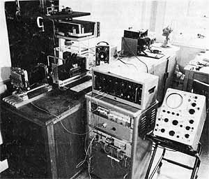
FIG. 2 First bench test apparatus to test the idea of running cross-correlation sampling, for improving telescope images.
We collected all sorts of bits and pieces (including my gramophone amplifier) to set up a bench test experiment to try the idea out. (Fig. 2). So far as possible we used available equipment, but we had to make a 'sampling shutter', capable of operating on demand from electrical pulses, given by mismatch signals from the photo-cell behind the Master Negative. Bill Matthews and I built the first sampling shutter (later improved by Stephen Salter) using a pair of electro-magnetic vibrator units. These were mounted opposed to each other, carrying thin squares of metal, each a half-square. When drawn apart a square hole was revealed, allowing light to pass; when drawn together the hole closed, preventing light reaching the second camera during sampling. This shutter is shown in Fig. 3.
We built this first apparatus in six weeks. It worked! For slowly oscillating images (moved with an oscillating Perspex plate in the light path) or later with random disturbance given by an agitated water bath, which proved a good simulator of atmospheric disturbance, we obtained very noticeable improvement with the sampling technique.
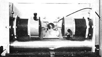
FIG. 3 First sampling shutter. This consists of a pair of electro-magnetic actuators (at right and left) which draw apart a pair of half squares (hidden behind front element of lens), when a close match between image and negative is signalled from photocell.
The following brief paper, which appeared in Nature, first described the idea, and the initial bench tests with the first crude apparatus. This led to our getting support, and help from many people, allowing us to build and test an instrument suitable for trials on telescopes. Would it - will it - reveal new secrets?]
It is well known that images in astronomical telescopes are shifted and degenerated by atmospheric disturbance. This becomes extremely important with large apertures and high magnifications: the disturbances prevent the detailed photographs which would be expected from the theoretical resolving power of large instruments. The disturbances take several forms: (1) The image may be shifted as a whole, in any direction, with varying frequency and amplitude. (2) Parts of the image may move in different directions simultaneously. (3) The image may be degenerated, especially with large aperture instruments, when the effective wave-length of the disturbance is less than the diameter of the objective. This produces a 'milkiness' of the image. This is quite different from the effect of shift when seen visually, though it may appear similar in a long-exposure photograph when the shifts produce blurring of contours and loss of fine detail.
It seems that visual observation can be preferable to photographic recording in lunar and planetary work, because the effects of the shifts of images can to some extent be avoided by visually sampling those moments when the agitation of the images is least marked. The purpose of the technique described here is to enable photographic telescopes to select moments of quiescence to build up a correctly exposed photograph.
It is clear from the kinds of disturbances encountered that any attempt to compensate the disturbances by introducing equal and opposite movements of the image on the plate will be unsatisfactory, when movements can occur in several directions in different parts of the image. Further, to get a servo-system to perform this task it would be necessary to feed it with information of the direction and velocity of the shifts, which is extremely difficult, while the servo itself would be subject to some over-shoot and tremor.
The technique under investigation is to take, first of all, a long-exposure photograph of the (atmospherically disturbed) image. The resulting photograph is statistically correct, in the sense that the major features will fall near the centre of intensity gradients produced by the random disturbance of the image. But, although the position of the contours will be nearly correct, fine detail is lost, hence the problem. This long-exposure photograph is processed, and the resulting negative is placed in its original position in the optical system, so that the fluctuating image now lies on the transparent negative. The image is now almost entirely cancelled by its negative. It is, however, most completely cancelled when the image most nearly corresponds to the negative. As the image is displaced, by the atmospheric or other disturbances, there is an increase in intensity. This is detected by a single photoelectric cell which covers the entire image plane, and so receives plenty of light. We can thus detect the presence of any shift of the image - though not the direction of shift - from increase in the output of the cell. The output rises with any discrepancy of the image from the statistically correct 'master' negative - not only shifts but also loss of focus and the 'milkiness' produced by regions of different refractive index smaller than the aperture of the instrument. (This last point I have established by means of a ripple tank.)
Having attained a signal indicating disturbance from the statistically correct image, it is a simple matter to use the signal to produce a second photograph free of disturbance. This may be done by using a second camera which shares the image with the first, by means of a beam splitter. This second camera is fitted with an electrically operated shutter which opens only when the output from the photocell is near its minimum value, corresponding to a close fit of the fluctuating image with the master negative.
In this way we separate informational integration from the integration of energy needed to expose the final picture, which is built up from many short exposures occurring whenever the image is close to the 'master'.
The preliminary experiments are limited to simulation of atmospheric disturbance, by placing an oscillating 'Perspex' sheet between the object and the optical system, and a ripple tank.
The beam splitter is a half-silvered mirror placed at 45?, so that the second camera (an 'Exacta' 35-mm. single-lens reflex) is provided with the same image as the large camera carrying the master negative and the photo-cell. The second camera is fitted with a specially made shutter, consisting of a pair of electromagnetic vibrator units (Advance type VI) which drive a pair of metal vanes shaped to form a square opening, increasing in size as the vanes are withdrawn by the opposed vibrator units. The circuit consists of an oscillator (400 c/s) allowing a.c. amplification from a bridge which is unbalanced by the photo-cell changing in resistance with increasing light, when the image loses register with the master. The amplified output is rectified, and used to energize the vibrator units to close the shutter.
An example of how a shifting image is improved is shown in Figs. 4a and b. Fig. 4 a was obtained from a long exposure of the Moon model while the 'Perspex' plate was oscillating about a vertical axis, to produce horizontal disturbance. The degeneration along the horizontal axis is very apparent. Fig. 4b shows the improvement obtained - the optical conditions being identical - when the shutter system is switched on. Some degeneration on the horizontal axis can still be seen: this may be further reduced by increasing the gain of the amplifier.
The improvement shown is given by a shutter open/closed ratio of about 6:1. This may be increased by increasing the gain in the present arrangement, or by introducing a gate, working the shutter as an all-or-none device. It is important to note that the improvement is from a blurred master negative identical with Fig. 4a since it was taken through the disturbance.
We are now simulating atmospheric disturbance with a layer of water agitated by an electromagnetic vibrator, driven from a low-frequency noise source. The resulting disturbances appear very similar to those experienced with an astronomical telescope. It remains to discover the efficiency of the technique under these more realistic conditions. It might then be directed to the Moon and the planets.
| (a) | (b) |
FIG. 4 First improved picture. (a) not sampled; (b) sampled. The disturbance is given by an oscillating perspex plate, using the first apparatus, as shown in Fig. 2. [NOTE: The limitations of reproduction for images in this publication renders the improvement seen in the actual images more difficult to see.]
It was clear that to get further, we would have to embark on a major instrument design and building project: we would have to stretch our abilities and resources to the limit. It would take an unpredictable amount of time, money and effort to build an adequate instrument to make use of the idea effectively on a telescope. Also, we were hardly in the right kind of department - was this anything to do with psychology? (Actually, I now think that relating real-time data to a stored average may be extremely relevant to psychology; but I did not realise this at the time.) Would building a telescope camera be acceptable in the context of experimental psychology? Here we were particularly fortunate to be in the University of Cambridge, for Cambridge has a long and well-justified tradition of tolerating individual foibles. The head of the department, Professor Oliver Zangwill, was tolerant, and the department of astronomy gave every encouragement and help - allowing us the sole use of a telescope for a year. This was the much loved century-old Thorrowgood refractor, in the care of Dr David Dewhurst, who was especially concerned with our project. The telescope is small, only eight inches in aperture; but it is sturdily built and well able to take the weight of our apparatus. We added a ring of red safe lights in the dome and replaced the nineteenth-century weight-driven drive clock with a synchronous motor driven from an accurate oscillator and - the fact is - we had an awful lot of fun and excitement in that little dome with its old brass telescope. Lastly money - we were given a generous grant from the Paul Fund of the Royal Society. This Fund exists to support the development of novel apparatus likely to be of scientific importance but of limited financial interest. It was a great day when all this came through, and we were able to plan our instrument for making more effective use of telescopes for probing the sky.
FIG. 5 Layout of second sampling camera. This is a side elevation of the sampling camera showing all main optical and mechanical features, except the final-picture camera which is mounted at (e).
(a) Mounting flange, for fixing camera to a telescope.
(b) Mixing cube, 5000 of light to the master plate (f), and 5000 to the final-picture camera (e), (not shown) via the sampling shutter, (d).
(c) Secondary lens, imaging telescope objective at:
(d) the sampling shutter, shown in Fig. 7, allowing, when open, light to reach:
(e) the final picture camera (not shown).
(f) is a manually operated photographic shutter for exposing:
(g) the master plate, whose holder is shown in Fig. 6.
(h) While sampling, light passes through the shutter (f) and the master plate (g) via mirrors h1 and h2 to:
(j) the photomultiplier which provides signals to the analogue computer, to actuate the sampling shutter (d), when the image most closely matches the master negative when the photomultiplier current is near a minimum: indicating that the fluctuating image is most nearly undisturbed - and so is the best representation of the object.
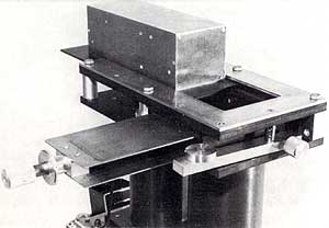
FIG. 6 Master Negative slide holder and locating system. The Master Negative plate is in the back square hole (top front) which is revealed when the mirror assembly (top), which sends light to the photomultiplier in further tube, (bottom) is slid back, as in this picture. The double dark slide is shown withdrawn, as when the plate is being exposed or when sampling is taking place. (The mirror assembly would however be slid forward over the Master Negative.)
The sampling camera was built by Stephen Salter, a dedicated engineer who applied all his skill. A darkroom was set up in the Thorrowgood dome by Philip Clark, who did trojan work organising temperature baths and fixing up a high speed processing service for the master plates. All through that incredibly wet summer of 1966 we strived to get improved pictures through gaps in the clouds.
The apparatus may be seen in the following figures. The general design of the sampling camera is shown in Fig. 5 and details such as the master plate location system (Fig. 6), the high speed on-demand sampling shutter, which presented the greatest difficulties. The problem here was to provide on-demand exposures down to about one milli-second, and this by mechanical means is quite surprisingly difficult. (Photographic shutters 'cheat' by employing pre-wound springs providing stored energy, so that they are not truly on-demand; or focal plane blinds whose moving slits give short exposures to each part of the film, though the entire exposure is quite long). We were helped by the fact that the image forming light in a telescope crosses near the final image, to make a small cross-sectional disk, which may be occluded with a small aperture shutter. The size of this disk depends on the optics of the telescope, but is generally only about one tenth of an inch in diameter. By placing our shutter exactly at this position of minimum required aperture it proved possible to get sample exposures down to just over one millisecond, with electromagnetic actuators suitably matched to thin steel blades. The arrangement, designed and built by Stephen Salter, is shown in Fig. 7.
There may be no gain with a faster shutter (except for work on the sun) for there must be sufficient time to collect enough quanta for a reliable correlation estimate. We would however like to try switched image-intensifiers, as non-mechanical shutters. It would also be nice to avoid photographic processing for the Master Negative, by some kind of electronic image storage.
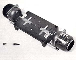
FIG. 7 Second sampling shutter, designed and made by Stephen Salter, using a pair of electromagnetic actuators (at ends) to deflect a pair of steel strips (feeler gauges) each having a small hole at its end: the holes coincide to allow light through when actuated by a sampling signal. (The feeler gauges are mounted with phosphor bronze pivot strips, in a mechanical matching transformer arrangement to give maximal efficiency.)
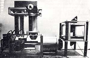
FIG. 8 Second sampling camera, on bench test. The randomly agitated water bath for simulating atmospheric disturbance is to the right with a pair of 90 prisms for passing the light from the object (off picture to the right) vertically through the water. The sampling camera is shown with its side plates removed, but otherwise complete, with the final - picture camera (partly hidden) at extreme left.
The camera can be seen on bench test in Fig. 8. A result, shown as a comparison pair of sampled and non-sampled pictures is shown in Fig. 9. The bench test improvement is really dramatic.
We obtained encouraging if not really conclusive results on the Cambridge telescope (Fig. 10) getting the kind of improvement apparent in Fig. 12 though this could have been due to chance improvements of the conditions between the sampled and unsampled pictures. We had enormous difficulty with the tracking of the telescope: we could only hope to get results when it was tracking the object (planet or moon) almost within the resolution of the telescope over a sampling period of about 30 minutes. This turned out to be extraordinarily difficult, with any telescope we have met, and has led to the building of a photo-electrically guided tracking corrector, which is now (Feb. 1972) being tested.
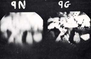
FIG. 9 Example of disturbed picture improvement by sampling. Both pictures are taken through the same disturbance (randomly agitated water) but 9G is sampled while 9N is a normal exposure. The unsampled, 9N picture is the same as the Master Negative used for obtaining 9G by sampling. So this gives a fair idea of the amount of improvement obtained on bench test. (Unfortunately there are technical problems which have, so far, prevented comparable improvement on telescopes. I believe these difficulties will be overcome.)
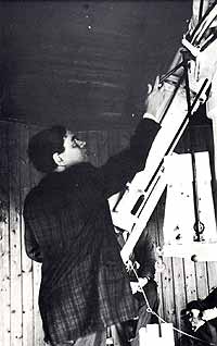
FIG. 10 The 8" Thorrowgood refractor at the Cambridge observatory, with the author. This was the first telescope used for trials. It is over a hundred years old, but an excellent instrument of its class.
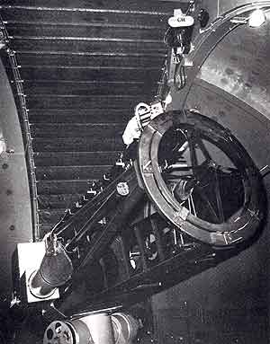
FIG. 11 The New Mexico telescope with the sampling camera and Stephen Salter (wearing arctic clothes) at the Newtonian focus. (It was very frightening up there!)
The first telescope trials on large instruments started with a joint working party of the American National Academy of Science and the U.S. Air Force, held over six weeks at the Witney Mansion at Cape Cod. This was a memorable time, with experts in optics, meteorology, mathematics and physics gathered to explore possible ways of improving images. It led to an invitation to try our apparatus out on the satellite tracking station, on a mountain in New Mexico. Fig. 11 shows the sampling camera, with Stephen Salter in arctic dress, on the telescope. The expedition was largely unsatisfactory, though we learned a lot. We then worked on the 61 inch reflector of the Lunar and Planetary Laboratory, Tucson, Arizona, through the kindness of its Director, Professor Gerard Kuyper. This also was a fascinating experience, and was more rewarding scientifically. But we were still troubled by tracking problems - which we hope will soon be resolved. So the present state of affairs is that we have a method and an instrument which works; provided its image is not allowed to drift systematically from its position of average register with its Master Negative reference. When this happens, the autocorrelation system breaks down and is useless. It is however perfectly possible to prevent this happening - and then we may get a new view from Earth of the stars.
 |
 |
| (a) | (b) |
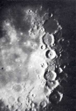
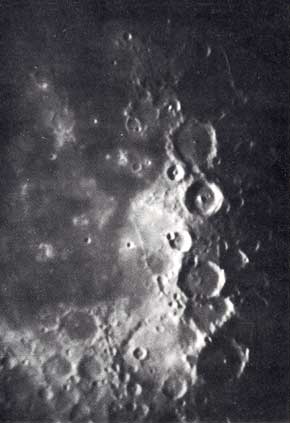
FIG. 12 Unsampled (a) and sampled (b) pictures of the moon taken with the 8" Thorrowgood refractor at Cambridge. There is a marked improvement, though less dramatic than improvement obtained with the same equipment on bench test (see Fig. 9). (It is possible for 'improvement' to be due to chance improvement in the seeing conditions between the two exposures, though these were taken within minutes of each other). Seeing conditions are so variable und cloud cover so frequent in the British Isles that we prefer to use bench tests, with repeatable controlled disturbances, for finding the optimum sampling strategy, master plate density and minimum acceptable object intensities. Also, the problem of sufficiently accurate tracking is avoided while effects of known tracking errors can be established. This has led to the building of a photo-electrically guided tracking corrector, which is being (1972) bench tested in preparation for telescope trials.
![]()