| PAGE 1 OF 2 | [1] [2] | DOWNLOAD PDF |
Richard L. Gregory and Priscilla F. Heard
Reprinted by kind permission of the Editor from: Quarterly Journal of Experimental Psychology (1983) 35A, 217-237
Brain and Perception Laboratory, University of Bristol, Department of Anatomy, The Medical School, University Walk, Bristol BS8 1TD, England
Helmholtz (1867) described as "irradiation" the apparently greater size of a white compared with a dark square, or disc or whatever of the same physical size. The illusory size difference is reversed at low contrasts (Weale, 1974). It is also known that rapid increases in brightness gives apparent movement (gamma movement), though there is no agreed explanation for either phenomenon.
When narrow bordering stripes arc added, further systematic phenomena occur. With intensity modulation of an edge-striped grey rectangle, which has a dark stripe on the left side and a light stripe on the right (which is similar to figures used by Stuart Anstis and Brian Rogers), the entire figure shifts, with reversed motion when the background luminance is modulated. By presenting a pair of such figures, mirror reversed one to each eye and fused stereoscopically, the question may be asked: Do these illusory shifts produce stereo depth? The answer is surprising: stereo is produced - but at the cross-over with luminance of the central grey rectangle with the background the depth change is opposite to that given by normal, non-illusory, opposed lateral shifts. We interpret this anomalous stereo depth as a switch of which edges of the stripes are fused, with the change of relative contrast of the edges of the dark and light stripes as the figure-background contrast is changed.
Measures of static shift, lateral movement, and stereo depth, give somewhat different functions. These are considered in terms of different signalled positions, stereo depth, and movement. This study brings out the importance, for explaining such perceptual anomalies, of distinguishing between neural signal channel characteristics and which stimulus features from the display are selected and accepted for perception. Although conceptually clearly distinct these are all too easily confused in psycho-physical experiments.
Introduction
Are visual movement, seen positions of edges, and disparities for stereoscopic depth, all signalled by the same channels? If there are separate channels - presumably with different characteristics appropriate for these very different functions - how is registration at edges maintained, or attained against signalling discrepancies, to hold the visual world together?
It may also be questioned - as a very general question for psychophysics - whether the same or different features are accepted from a viewed display or object for signalling for example movement, position, and stereoscopic depth. Different channel characteristics and different selections from the stimulus pattern, though these are logically quite distinct, may very easily be confused in psychophysical experiments. In either case - different channel characteristics or different selections of features- - we would expect loss of registration in perception between movement, position, and depth; unless there are locking systems for holding the visual world together, as has been suggested with some evidence (Gregory and Heard, 1979).
A simple display of a vertical pair of contiguous narrow stripes, one dark, the other light, appears to move dramatically sideways, as a whole, as the striped display or its background illumination is varied around the mean luminance of the stripes. The direction of movement is always: the light stripe edge leading while the background luminance is increasing. While the background luminance is decreasing the dark stripe edge leads. Conversely, varying the illumination of the striped figure with the background luminance held constant produces movement in the reversed directions: now the light edge leads with decreasing display luminance, and the dark edge leads with increasing display luminance. If the luminance of the background and figures are simultaneously varied in opposite directions, then the apparent movement occurs similarly. There is no movement if both change equally together. These phenomena occur only with narrow stripes. Effects with broad edge stripes (above about 10 mm of arc) will not be discussed in detail here. For these experiments we separated the light and dark stripes with a grey rectangle of intermediate luminance. Each striped figure (the narrow light edge stripe, the central grey rectangle and the narrow dark stripe) remains unchanged in luminance throughout, as the background is changed or modulated for these observations and measurements.
Although very similar, this is somewhat different from the display used by Anstis and Rogers (1975), Rogers and Anstis (1975), and Rogers (1976). In their experiments, which are closely related to the phenomena and data reported here, they also use a central grey region bordered by a light stripe on one side and a dark on the other. Their display is given by fading a projected transparency of a dark rectangle (or disc) in a bright background, into its photographic negative (a bright rectangle or disc in a dark background) which is slightly displaced to one side. This produces a rectangle or disk where the opposite contrasts overlap, with a narrow stripe on each side, one light and the other dark. With this arrangement the central region changes in luminance reciprocally with the background, within the luminances of the dark and light edge-stripes which remain at constant luminance. Our display is simpler, for only the background luminance changes, and it allows a greater range of figure/background contrasts. Anstis and Rogers claim that their apparent movement, positional shift, and stereo-depth all obey essentially the same functions. We find significant, indeed dramatic differences in these functions. It is primarily these differences that will be discussed here.
Experiments
Stimuli
In our experiments, one of the striped rectangle figures was placed above and precisely in line with the other, immediately below it, which was exactly the same except that it was right-left reversed; so that the upper had its light stripe on the right and the lower on the left (Fig. 1).This arrangement doubles the movement and shifts effects, and it provides a convenient display for observing and measuring the static displacements and stereo depth.
The rectangles were 1.5 deg. in height, separated by 0.5 deg. vertically. The stripe width was 1.8 min of arc and the width of the inner grey rectangles was one degree. The background subtended 11.5 deg. horizontally and 6.0 deg. vertically. The viewing distance was 2 m. The stripes were made photographically, with high precision, their widths being checked with a travelling microscope.
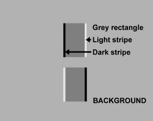
FIGURE 1. The edge striped rectangle figures. These are precisely vertically aligned. The lower figure is the mirror image of the upper. The widths of the narrow dark and light edge stripes are equal, subtending 1.8 min of arc to the eye. The luminance of the background was varied, the rectangle figure illumination being held constant in these experiments.
Measurement of the illusory movement
The dramatic illusory lateral movements of the vertical borders
were measured by matching with true movements of a pair of oscillating
rectangular line figures generated on a C.R.T., which were optically
introduced beside the display rectangles. They were oscillated
with controlled amplitude, and phase locked to the luminance modulation
producing the illusory movement. They were viewed simultaneously
with the illusory movement, which was produced by modulating the
background luminance sinusoidally at 1.5 Hz with a 0.2 log unit
(60%) depth of modulation, for various mean luminances of the
background (Figs. 2 and 4).
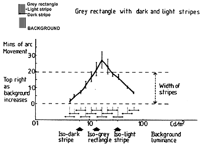
FIGURE 2. Graph showing the amplitude of the illusory movement, produced by a 0.2 log unit modulation of background luminance, through a range of background luminances. The illusory movement was measured by matching with a dynamic oscilloscope display optically superimposed beside the illusorily moving striped rectangles. The oscilloscope display consisted of two vertically aligned rectangles, of similar dimensions to the test rectangle figures, which oscillated horizontally with amplitude controlled by the subject, atthe same frequency and in phase with the background luminance modulation, which produced the illusory movement of the striped figures. The modulation was achieved with a rotating polaroid; which also modulated a second light source activating a photo-detector to drive the oscilloscope display, for measuring the illusory movement by setting its amplitude to match the illusory movement. There were seven subjects and each gave three matching judgements for each point.
We find that the illusory movement is always greatest when the mean background luminance lies between the edge stripe luminances (Fig. 2). There are no obvious phase changes of illusory movement with changes of the mean modulated luminance.
The direction of the apparent movement (light edge leading while the background luminance is increasing) is the same as found by Anstis and Rogers; but they did not measure its amplitude.
Measurement of illusory displacements
Static displacements were revealed as vernier misalignments of the upper and the lower (right - left reversed) striped rectangle figures. The vernier displacements, which were only just discernible, were measured by nulling. This was accomplished by shifting the lower figure laterally, with a swinging optical flat, to produce - by offsetting the illusory shifts - precise apparent alignment of the upper and lower figures.
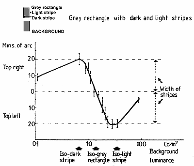
FIGURE 3. Graph to show the lateral static displacements (vernier offsets) between the upper and lower rectangles, at selected background luminances. Seven subjects adjusted a glass plate. rotatable around its vertical axis, placed in the optical path of the left eye for the lower rectangle figure, until both rectangle figures appeared to be precisely vertically aligned. There is seen to be maximum vernier displacement at isoluminance of the background with the dark or the light edge stripes (when they become invisible) and the offset is approximately equal to their widths. The displacement is zero when the background is isoluminant with the central grey of the rectangle figures.
The measured static displacement (Fig. 3) obeys a very different function from the movement. As the background is set to successively higher values, the direction of the displacement reverses at critical luminance values, though movement continues without change of phase with modulation for all luminance values. With background luminance below the luminance of the dark edge stripes, and with background luminance above the light stripe luminance, the movement and the displacement are in the same direction. When the background luminance lies in the range between the stripes, the movement and the position (as measured by vernier offset) are dissociated - they now occur in opposite directions.
Here our results differ from Anstis and Rogers's (1975). They presented three conditions:
(i) a black and a white square in contact;
(ii) a dark grey and a light grey square separated by a black stripe;
(iii) the light and dark grey squares separated by a white stripe.
They report shifts of the black and white stripes relative to the black/white interface of the first condition - in the same direction as their observed movement. (Movement was generated by a stimulus transition from condition (i) to conditions (ii) and (iii).) These stimulus conditions are equivalent to our display when the background luminance is equal to the white stripe or the black stripe. But here we find that the vernier shift is in the opposite direction to that reported by Anstis and Rogers. They only presented two luminances of their square: a full range of luminances reveals a different picture - that the vernier shift is opposite in direction to the movement. This is seen in the vernier and movement curves of Figure 6.
Measurement of the illusory stereo depth
Having found that the functions for amplitude of illusory movement and static displacement are essentially different, we now asked the question: can stereo depth be produced by the illusory movements, or by the illusory displacements - when presented in opposed directions to each eye? We already have opposed directions of illusory movement and static displacement for the upper and lower stripe figures. This occurs because the dark and light stripes are on opposite sides of the rectangle figures; the upper rectangle having its dark stripe on the left, while the lower rectangle's dark stripe is on the right. All that is necessary to test for stereopsis is to add an identical pair of these rectangle figures, mirror reversed to one eye (the left), while the other (the right eye) views the rectangles without reversal. Mirror reversal, of both the upper and lower striped rectangles for the left eye, is achieved by a Dove prism (Fig. 4). The resulting slight increase in effective optical path length, and slight loss of light, is corrected for the right eye with a compensating glass block. Thus, the illusory movements and displacements were presented in horizontally opposed directions to the eyes (for experimental convenience from only one pair of rectangle figures) to discover whether they produce stereoscopic depth; and if so how the movement, displacement, and stereo depth are related.
Stereo depth was measured in two ways: first, by luminous depth markers (L.E.D. line displays) introduced optically with a 45 degree half-silvered mirror, placed before the Dove prism so that the marker distances were seen by normal stereopsis unaffected by the Dove prism's mirror reversal to the left eye. The markers were set for distance by the subject, using electrical control. For the second method, the depth seen between the upper and lower rectangles was reduced to zero by nulling: by optically shifting one of the rectangles sideways, with the swinging glass plate which was also used for measuring the vernier misalignments (Fig. 4).
Stereo depth was clearly seen between the upper and lower rectangles in the conditions of opposed illusory displacements to the two eyes. Depth was readily measured by the matching or by the nulling method (Fig. 5). The depth observations and measurements were extremely stable - except when the background was isoluminant with the central grey rectangle, when the depth was labile, and almost impossible to measure either by the movable markers or by the nulling technique.
In an earlier experiment one of us (Gregory, 1979) reported absence of stereo depth with binocularly opposed illusory movements of disk figures with light and dark edges. These were similar to the rectangles with edge stripes used here, though the earlier observations used a variable colour interference filter to control the luminance ratio between a differently coloured (green) background and (red) disk figures. This technique was adopted so that standard colour projection slides could be used. The absence or near loss of stereo in these conditions, we attribute firstly to the use of colour, as Stereo was absent or reduced with only colour contrast (Lu and Fender, 1972; Gregory, 1977) and secondly to the disk figures being somewhat less effective for stereo than the rectangles which have long vertical edges. We regret that this reported observation may have been somewhat misleading as it does not generalize to all conditions.
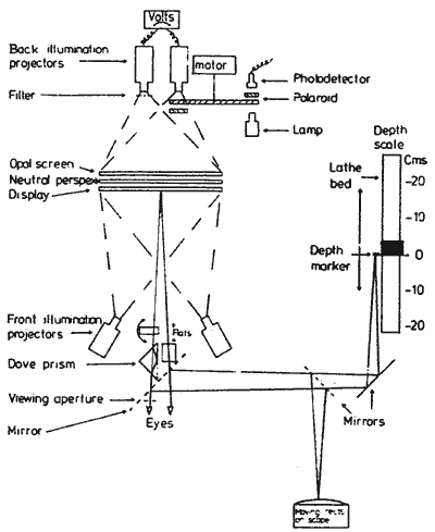
FIGURE 4. Experimental apparatus, showing
the component parts used in these experiments; though not all
were used at the same time.
(1) The Dove prism was used in
the stereo experiments to give right/left reversal of the rectangle
figures to the left eye (a glass block was used to equalise the
optical distance for the right eye).
(2) The half silvered mirrors,
placed at 45 degrees to the line of sight introduced the binocularly
viewed L.E.D. depth markers (mounted on the motor driven saddle
of the lathe bed optical bench), for measuring depth; and also
the oscilloscopes moving line rectangles, which were used for
measuring the illusory movement.
(3) The glass plate, placed in
the optical pathway of the lower rectangle figure. could be rotated
around its vertical axis. It was used with binocular viewing of
the rectangle figures (mirror reversed to the left eve) to null
the depth difference between the upper and lower rectangles; and
monocularly to null the lateral shift between the upper and lower
rectangles for measuring vernier displacement.
The functions found here describing the vernier displacements and the stereo depths do not agree. When the background is set at successively higher values lying within the luminances of the stripes (when all the contours are clearly visible), the stereo depth becomes greater as the Static shift becomes less. When the background was changed from slightly darker to slightly lighter than the central grey, there was minimal vernier displacement; but here there is a dramatic switch of depth. The upper rectangle moves forward and the lower rectangle backward. This is especially dramatic as the difference in distance of the rectangles is maximum when the background is just off isoluminance with the grey, though at exact isoluminance stereo depth is entirely lost.
These findings clearly show a dissociation of the stereo depth from the static displacements measured by vernier offset. The vernier displacement reverses direction as the background luminance crosses the luminance of the dark or the light stripes (Fig. 3); but the depth continues in the same direction while the background crosses isoluminance with the stripes.
When the background luminance is modulated sinusoidally, the upper and lower striped rectangles move backwards and forwards, so that one approaches as the other recedes, to oscillate in depth exactly out of phase with each other. This dramatic movement in depth as the intensity is modulated across isoluminance is seen dynamically in the critical luminance range where static depth measurements cannot be made. This is represented by the dashed line in Figure 2. Throughout the background range where measurements can be made, the seen depth changes with modulation of the background luminance correspond to the static depth measures. Stereo depth is dissociated from the sideways movements when the background crosses isoluminance with the central grey (Fig. 2). This is where there is dramatic switch in depth. This depth switch would normally be given by a physical disparity shift of as much as four stripe widths, over this veer small change in background luminance around the luminance of the central grey. For normal stereo giving the same change of depth, the directions of the opposed lateral movements in each eye would have to be in the opposite directions to these illusory lateral movements.
It is difficult to make direct comparisons between these stereo depth measurements and those of Anstis and Rogers (1975), and Rogers and Anstis (1975), as the experimental conditions were different. Anstis and Rogers presented a constant luminance (positive) rectangle to the left eye. The right eye was given static stages from a dissolve of a positive rectangle into a slightly displaced negative rectangle. This generates their illusory movement. The first stage of this dissolve was the same as the left eye's rectangle, the later stages of the dissolve contained a greater proportion of the negative and correspondingly less of the positive. They found a change in depth through this sequence which was in the same direction as the movement; but when the right eye contained a greater proportion of negative than positive measurements could no longer be made. At this point there was rivalry and fusion broke down. These results agree with half of the function we have reported above; as we too find that movement and changes in stereo depth are in the same direction - until our background luminance crosses isoluminance with the central grey rectangle. Anstis and Rogers were unable with their display arrangement to measure depth across this, as it turns out, critical luminance range.
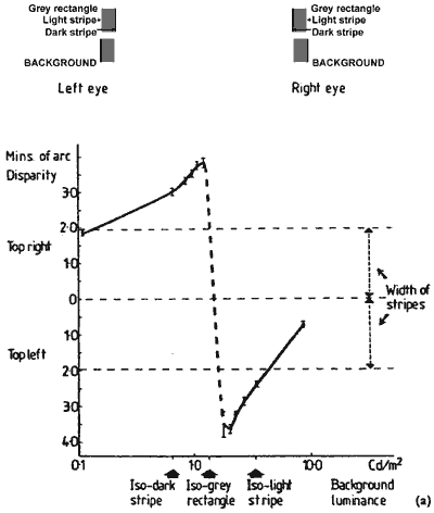
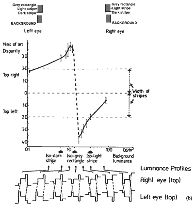
FIGURE 5. The graphs show the depth between the upper and lower rectangle figures at selected background luminances. In graph (a) depth is measured by matching with depth marker lines. The depth measures were converted into equivalent disparity units. In graph (b) the depth was measured by shifting the lower rectangle sideways with a glass plate to the left eye to null depth between the rectangles. This gives a disparity measure directly, which was halved so as to be appropriate for the figures to both the eyes. When the background is darker than the grey rectangles, the top one appears behind the lower one. There is a dramatic switchover in depth as the background becomes lighter than the grey rectangles: the top comes forward and the lower one back. The luminance profiles of the top rectangle figure, to the right and left eyes, are shown at selected background luminances. The slashed and dotted lines show the alternative same sign fusion edges for the stereo depth. The slashed lines show the pair of edges that have the greater contrast. When the background is isoluminant with the grey rectangle both pairs of fusion edges have the same contrast.
Comparison of the three measured functions
The three measured functions - amplitude of movement, static shift, and stereo depth - are plotted for comparison with the same coordinate units in Figure 6. The illusory movements were produced by 0.2 log unit, at 1.5 Hz modulation of the background luminance, and measured by matching with the C.R.T. display. The two other functions were measured at set background luminances. The depth and vernier offset were measured at the end points of the background luminance modulations used for producing the illusory movement; and the shifts in depth, and the vernier offset over these ranges of luminance change, are plotted with the movement measures for comparison on the same graph (Fig. 6).
It will be seen that for background luminances less or greater than the dark and light edge stripes, the three functions are the same in direction; but the amplitude of the movement is greater than the amplitude of the static shifts. With background luminances between the luminances of the light and dark stripes, the functions diverge, and the divergences are extreme around isoluminance with the central grey. Here movement is maximal while depth change is also maximal; but, as we have said, it is in the opposite direction from what would be given by equivalent physical movements viewed stereoscopically.
So there are discrepancies, both for direction and extent, between the three functions.
continues
