
| PAGE 2 OF 3 | [1] [2] [3] | DOWNLOAD PDF |
Richard L Gregory, Priscilla Heard
From: Perception, 1979, volume 8, pages 365-380
Brain and Perception Laboratory, University of Bristol, Department of Anatomy. The Medical School. University Walk, Bristol BS8 1TD. England
continued
2 Method
2.1 Apparatus
The following variables could be controlled and the effects measured:
(a) Width of the dividing mortar lines.
(b) Luminance of the mortar lines.
(c) Luminance contrast of the dark and light tiles.
(d) The offset of alternate rows of the tiles (allowing the display to be changed, continuously, to a chessboard with variable-width mortar lines between each row of tiles).
(e) Colour could also be controlled, though this will not be discussed here. [The illusion disappears with isoluminant coloured tiles. cf 'law' (viii).]
(f) The wedge distortion was measured by adjusting and matching a pair of variable-convergence lines, surrounded by a circular aperture placed immediately above the Café Wall display (figure 7).
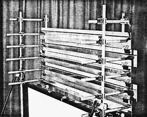
Figure 5. Back view of the main display, showing the aluminium strips retained with springs against the vertical frame supports. The mortar-line gaps are set with spacers placed on top of the retaining bulldog clips.
Five accurately parallel strips of aluminium, 7.5 cm wide and 92 cm long, were cut with a precision guillotine. They were made rigid with aluminium strips bent to an L-shape and glued along their length. The strips were mounted as shown in figure 5. They were free to slide sideways, and were kept in place with light pressure from compression springs which held them against the front two vertical rods of the support frame. Alternate dark and light tiles, 7.6 cm wide, were stuck onto the strips. The aluminium strips of tiles were spaced apart to give any required mortar-line width, with shims (or coins) placed between the strips, as shown in figure 5. This display was masked by a black rectangular surround showing eight tiles per row. (This seems preferable to a circular mask as the figure is of special interest, through having only parallels and right angles. A circular surround was however used for the matching lines in order to avoid comparison horizontals.)
The mortar-line luminance was given by Variac-controlled slide projectors illuminating a diffusing screen behind the display strips. Since these were opaque, only the gaps between the strips, giving the mortar lines, were illuminated by these back projectors. The colour temperature changes were regarded as acceptable.
For these experiments it was important to provide a contrast range as wide as possible between the dark and light tiles; and to ensure that the mortar lines could be set not only to any luminance over this range, but significantly darker than the dark tiles or lighter than the light tiles. To make it possible for the mortar to be darker than the dark tiles, these were made of white paper. This required that the light tiles be made of a material having very high reflectance, for it was important to provide as high as possible luminance contrast between the dark and light tiles.
This was achieved by making the light tiles of retroreflecting material, having very closely spaced microscopic corner cubes. This gives effective autocollimation, the incident light being reflected back to the source, as in 'cat's eyes'. We therefore obtained virtually the source intensity for the luminance of the white tiles, and a variable luminance contrast ratio between the dark and light tiles greater than could perhaps be attained in any other way.
There were two ways available for adjusting the contrast between the dark and light tiles. First, since the retroreflecting material does not depolarize the incident light, we could employ variable-angle cross polarization. This, however, hardly gives a range of one order of magnitude, and we were anxious to explore a wider range of luminance. Moreover, it has the disadvantage that the subject must view the display through a polarizing filter, with considerable optical loss due to scatter. So this method was not adopted.
Figure 6. Layout of display apparatus. The observer (left) views the display monocularly. The pair of on-axis projectors are provided with right-angle prisms in order to reduce the separation as much as possible. (Beam splitting was not used as this introduces scatter and glare.) The pair of off-axis projectors were in fact above and below, respectively, for lack of space. They served with the on-axis projectors to give variable contrast between the dark and light tiles, owing to the different directional reflectance characteristics of the white paper (the dark tiles) and the retroreflecting material (the light tiles). This is explained in the text. The three projectors at far right provide the mortar-line illumination, with trans-projection of the screen behind the display. (Three projectors are used to minimise the 'hot spot' from the central projector, which is endemic to trans-projection.)
The second method open to us may be novel. It made use of another feature of the retroreflecting material: its highly directional reflectance. To obtain the greatest luminance, a pair of light sources (slide projectors) were placed as close together as possible either side of the viewing position (figure 6). The bright tiles were then very nearly as bright as the sources. We arranged a second pair of projectors at an angle of about 25? each from the viewing line, so that the efficiency of the retroreflecting material was, for these, greatly reduced; though the luminance of the dark tiles made of white paper remained almost unchanged, as paper does not have directional reflectance. With this second pair of projectors the retroreflecting material was actually darker than the white paper, normally producing the dark tiles, when the two sets of light sources were set to equal intensity. This made it possible to reduce contrast, not only to zero, but to cross the isoluminance point by varying the intensity ratio, continuously, of the on-axis and off-axis projectors. The tile contrast was thus set by using both pairs of projectors simultaneously. The range went from zero (or actually from reversed contrast) up to about 0.94, where contrast is taken to be
(L max - L min) / (L max + L min).
It is important, though it was by no means easy, to obtain uniform illumination for the tiles and the mortar. This was achieved mainly by using high-quality slide projectors with aspheric condensers. Since it is essential to be able to set the mortar luminance above the luminance of the light tiles at their maximum, and the retroreflection of the light tiles was far more efficient than the trans-illumination used for the mortar, there was no point in providing the brightest possible front projectors for the tiles. These were illuminated by two pairs of high-quality 150 W Leitz Pradovit projectors. The mortar was given by back projection, from a centrally placed Aldis 250 W projector, with a pair of 150 W projectors angled to give the most even illumination, as there is an inevitable 'hot spot' with back projection from the central projector. The back-projection mortar illumination might have been increased with advantage, to allow a still greater useful light-tile luminance for the extreme conditions of the experiment. Floodlights can be used to increase mortar luminance.
 |
 |
| Figure 7. The subjects' view of the Café Wall apparatus | Figure 8. The adjustable convergence lines for measuring the wedge distortion by matching. The lines consist of a wire whose ends are attached symmetrically either side of the centre of the large wheel, and pass over a pair of pulleys. As the large wheel is rotated the ends separate, or meet, and so the convergence changes. |
Measures of the wedge distortion were obtained by matching the (apparent) wedge angle with a pair of lines, adjustable in convergence, placed within a circular mask situated immediately above the Café Wall display (figure 7). The lines were in fact a single wire passing over a pair of pulleys, on the right side, having a fixed separation of 60 mm. The variable convergence, set by the subject, was given by the simple mechanism shown in figure 8. It was measured for each setting from magnified shadow-images of the wires, produced by a point source placed slightly above the wires and in front to cast their shadows by reflection from a vertical mirror placed behind the display onto the back of a translucent screen bearing the ruler. This arrangement made it possible to measure the separation, and so the convergence angle of the wires easily and accurately, for parallax errors were avoided with the shadow-images. By adjusting the distance of the vertical mirror the scale was magnified, exactly by a factor of two, to give the optimum movement of the wire images at the ruler, which was placed conveniently close to the experimenter, though the wires were hardly accessible for direct measurement. This kind of arrangement may be recommended for wider application.
2.2 Luminance calibrations
An S.E.I. spot photometer was placed at the viewing aperture to measure the luminance of:
(i) the back projection (mortar lines) at various voltage settings of the trio of projectors, with all other projectors switched off;
(ii) the dark and light tiles at various voltage settings for the pair of on-axis projectors, with the other projectors switched off;
(iii) the dark and light tiles at various voltage settings for the pair of off-axis projectors set 25? from the line of sight, with the other projectors switched off.
Calibration graphs were drawn for each of these, for deriving luminance values from the measured voltages under each condition. (It turned out to be necessary to measure the luminance of large sheets of the tile material, rather than individual tiles of the Café Wall itself, as light from neighbouring bright tiles produced significant errors by scattering of light within the photometer.)
2.3 Procedure
The subject's head was loosely restrained with a chin rest. The monocular viewing position, which is critical for this method (though not so critical as Maxwellian viewing), was determined by a 30 mm viewing aperture. The viewing distance was 2 m. Foveal fixation, with unlimited exposure time and free eye movements, was employed throughout so that the eye could be used as normally as possible. (In our experience peripheral vision is very difficult and fatiguing for subjects; and it is almost impossible to avoid 'cheating' with foveal fixations unless tachistoscopic exposures are employed. hut with these the eye is not used normally.) The distortion is. however, greater for peripheral vision, as Moulden and Renshaw (1979) report for the Münsterberg illusion. Comparison of the wedge distortion with the adjustable-convergence-angle lines was made sequentially, by looking up from the main display to the adjustable convergence lines above it, without changing the head position or moving the eye from the viewing aperture, as both the Café Wall display and the comparison lines were comfortably in view from this position.
Two kinds of responses were obtained: (a) matches of the distortion seen on the central row of tiles with the variable convergence matching lines: (b) verbal reports of the extent of distortion, without reference to the matching lines, on a four-point scale: 0 - for no distortion: 1 - for fleeting distortion, usually seen in peripheral vision, and generally associated with large eye movements; 2 - for a standing weak illusion, on the central row with foveal vision: 3 - for a standing set of alternate wedge distortions seen over the entire display without eye movements.
The five subjects used for the main experiment viewed the display with optical correction, when necessary with a selected trial lens placed in the viewing aperture. The Café Wall was set up at a 90? phase angle between alternate rows as shown in figure 7.
There were five conditions of luminance of tile contrasts.
I. zero (isoluminance) between the usually 'dark and 'light' tiles:
II. a dark - light contrast of 0- 11;
III. a dark - light contrast of 069;
IV. a dark - light contrast of 0-94;
(These were all presented with a light tile luminance of 86 cd m-2.)
V. the 0.94 dark - light contrast presented at a light-tile luminance of 7.6 cd m-2.
For each of these five luminance conditions, the subjects were presented with six values of' mortar width, subtending to the eye: 1, 2.7, 4.4, 6.1, 9.5, or 12.9 mm. These were presented at various luminances of the mortar lines: isoluminant with the dark or the light tiles, and at various intermediate luminances. Luminances outside this range were presented when necessary for establishing the upper and lower mortar luminances at which the wedge distortion disappeared.
continues
![]()